Thermostat Wiring: Complete Guide with Color Codes, Diagrams & Step-by-Step Instructions (2026)
If you have ever stared at the back of your thermostat and felt completely lost looking at a tangle of colored wires, you are not alone. Thermostat wiring confuses a lot of people — and honestly, it does not have to. Whether you are installing a brand new Nest thermostat, replacing an old Honeywell thermostat, or just trying to understand why your heating or cooling is not working the way it should, getting your thermostat wiring right is the key to everything.
In this complete thermostat wiring guide, I am going to walk you through everything you need to know. We will cover the thermostat wiring color code system, how to read a thermostat wiring diagram, the differences between Nest thermostat wiring and Honeywell thermostat wiring, how heat pump thermostat wiring works, and what a 4 wire thermostat wiring diagram actually means. By the time you finish reading, thermostat wiring will make complete sense to you.
Thermostat Wiring Color Code — The Complete Guide
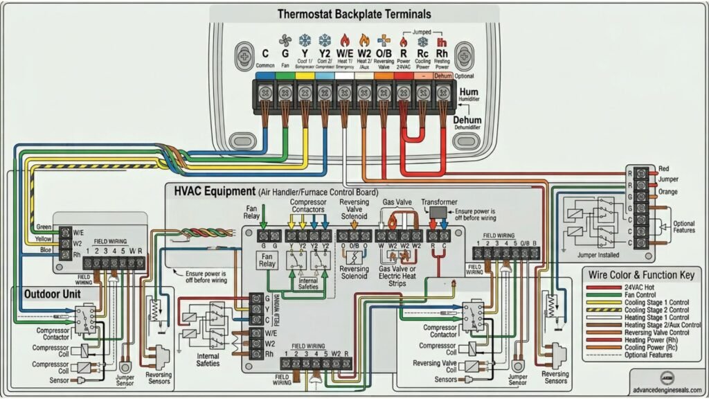
The thermostat wiring color code is a standardized system that tells you exactly what each wire does. If you understand the thermostat wiring color code, you can look at any thermostat wiring diagram and immediately know what is happening. Here is the complete thermostat wiring color code breakdown:
| Wire Color | Terminal | Function | System |
|---|---|---|---|
Red |
R / Rh / Rc | 24V power supply from transformer | All systems |
Green |
G | Fan control — turns fan on/off | All systems |
White |
W / W1 | Heating — stage 1 | Furnace / heat pump |
Blue / Black |
C | Common wire — completes 24V circuit | Smart thermostats |
Yellow |
Y / Y1 | Cooling — stage 1 / compressor | AC / heat pump |
Orange |
O | Reversing valve — cooling mode | Heat pump only |
Dark Blue |
B | Reversing valve — heating mode | Heat pump (some brands) |
Brown / Gray |
W2 / Aux | Heating stage 2 / auxiliary heat | Heat pump / 2-stage |
Red (second) |
Rc | Power for cooling circuit | Split systems |
This thermostat wiring color code is the foundation of every thermostat wiring diagram you will ever encounter. Whether you are looking at a Nest thermostat wiring diagram, a Honeywell thermostat wiring diagram, or a 4 wire thermostat wiring diagram, these same color codes apply across virtually every residential HVAC system in the United States.
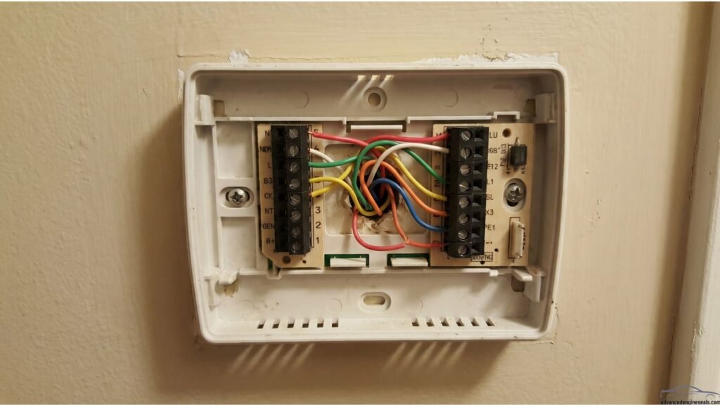
One important note about the thermostat wiring color code: while this color code is standard across most systems, older homes or non-standard installations sometimes use different colors. This is exactly why you should always check your existing thermostat wiring diagram or label each wire before disconnecting anything. Take a photo of your current thermostat wiring before you touch a single wire — that photo can save you a lot of headaches.
What Is Thermostat Wiring and Why Does It Matter?
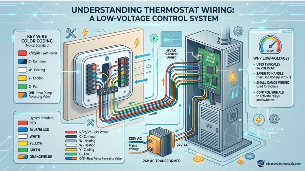
Thermostat wiring is the low-voltage electrical system that connects your thermostat to your heating and cooling equipment. Unlike the high-voltage wiring in your walls that powers lights and outlets, thermostat wiring typically runs on just 24 volts — safe enough to touch, but still something you want to handle correctly.
The thermostat wiring system is basically a communication line between your thermostat and your HVAC equipment. When you set your thermostat to 70 degrees and the house drops below that, the thermostat sends a signal through the thermostat wiring to tell your furnace or air conditioner to turn on. Each wire in the thermostat wiring system has a specific job, and each wire follows a standard thermostat wiring color code so that installers and homeowners can identify them correctly.
Getting the thermostat wiring wrong does not just mean your heating and cooling will not work right — it can also damage expensive HVAC equipment. That is why understanding the thermostat wiring color code and reading a proper thermostat wiring diagram before you start is so important.
Good news: thermostat wiring is one of the most beginner-friendly DIY electrical tasks in the home. The low voltage involved makes it safe to work with, and with the right thermostat wiring diagram in hand, most homeowners can complete the job in under an hour.
Nest Thermostat Wiring — Complete Installation Guide
Nest thermostat wiring is one of the most searched topics in the thermostat wiring world — and for good reason. The Nest thermostat is a fantastic smart thermostat, but its wiring requirements can trip up homeowners who are used to older, simpler setups. Let me walk you through Nest thermostat wiring step by step.
What Makes Nest Thermostat Wiring Different?
The biggest difference with Nest thermostat wiring compared to older thermostats is the C wire requirement. The Nest thermostat needs a continuous 24V power supply to run its Wi-Fi, touchscreen display, and smart features. Older thermostats ran on batteries and did not need this, but the Nest thermostat draws too much power for batteries alone to handle reliably.
In Nest thermostat wiring, the C wire (common wire) — usually blue or black — completes the 24V circuit from your HVAC transformer back to the thermostat. Without the C wire in your Nest thermostat wiring, the Nest may still work in some cases by borrowing power from other wires, but it can cause issues like the fan running unexpectedly or the system short-cycling.
Nest Thermostat Wiring Diagram — Standard Setup
For a standard heating and cooling system, the Nest thermostat wiring diagram looks like this:
| Wire Color | Nest Terminal | Function |
|---|---|---|
Red |
Rh or Rc | Power (24V) |
White |
W1 | Heating |
Yellow |
Y1 | Cooling / compressor |
Green |
G | Fan |
Blue |
C | Common wire (required for Nest) |
This is the standard 5-wire Nest thermostat wiring diagram for a typical forced-air heating and cooling system. If your existing thermostat only had 4 wires and no C wire, you have a few options: run a new wire from your furnace, use the Nest Power Connector accessory, or repurpose the G wire if you have a system where the fan runs automatically.
Color Code for Nest Thermostat Wiring Diagram
The color code for Nest thermostat wiring diagram follows the same standard thermostat wiring color code we covered earlier, with one important addition. The color code for Nest thermostat wiring diagram specifically highlights the C wire in blue — and this is the wire most people are missing when they upgrade to a Nest. When following the color code for Nest thermostat wiring diagram, always confirm the C wire is present before starting the installation. If it is not, check with Nest’s compatibility checker at nest.com before proceeding.
Honeywell Thermostat Wiring — Full Setup Guide
Honeywell thermostat wiring is the other big topic that homeowners search for constantly — and with good reason. Honeywell has been making thermostats for over a century, and their products are in millions of homes across the country. Understanding Honeywell thermostat wiring will help you install, replace, or troubleshoot almost any Honeywell thermostat model.
Honeywell Thermostat Wiring Color Code
The color code for Honeywell thermostat wiring follows the same standard thermostat wiring color code used industry-wide. The color code for Honeywell thermostat wiring is: Red = R (power), White = W (heat), Yellow = Y (cool), Green = G (fan), Blue = C (common). This is consistent across virtually all Honeywell thermostat wiring configurations.
Honeywell Thermostat Wiring Diagram — Standard Models
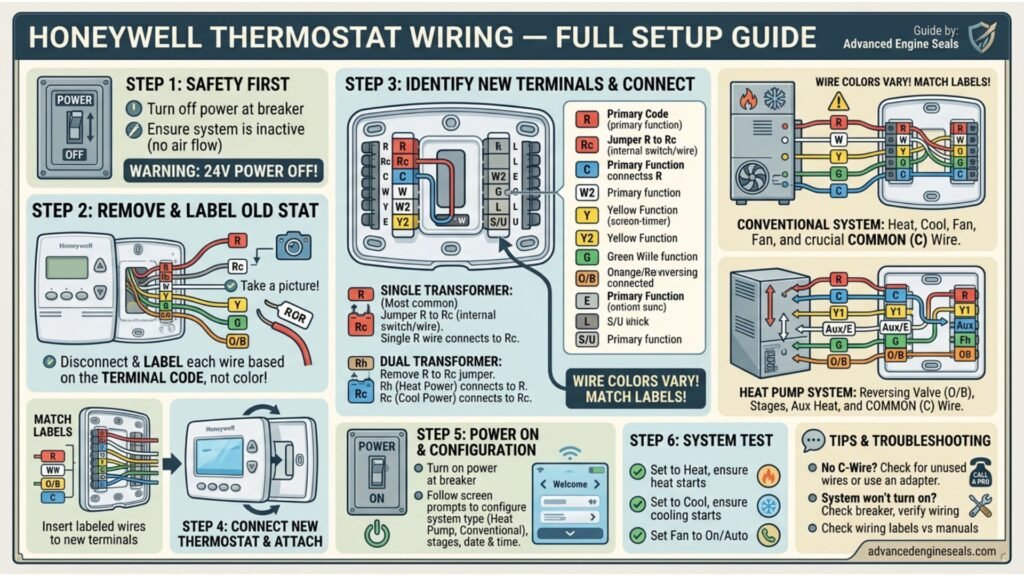
The Honeywell thermostat wiring diagram for their most popular models — including the T6 Pro, RTH7560E, and the classic T87 round thermostat — follows the same basic thermostat wiring diagram layout. In the standard Honeywell thermostat wiring diagram, you will see the same R, G, W, Y, and C terminals that appear in every other residential thermostat wiring diagram.
One thing that makes Honeywell thermostat wiring slightly different from other brands is how they handle the Rh and Rc terminals. In a split Honeywell thermostat wiring setup — where you have separate transformers for heating and cooling — you will see both an Rh terminal (red wire, heating power) and an Rc terminal (red wire, cooling power). In most standard Honeywell thermostat wiring diagrams, these two terminals are jumpered together from the factory. If you have a single transformer system, you leave the jumper in. If you have a dual-transformer setup, you remove the jumper and connect each red wire to its correct Honeywell thermostat wiring terminal.
Honeywell thermostat wiring tip: always download the specific wiring diagram for your exact Honeywell model from honeywell.com before starting. While the color code is standard, the terminal layout and available features vary between Honeywell thermostat models.
Heat Pump Thermostat Wiring — What Makes It Different
Heat pump thermostat wiring is more complex than standard furnace and AC thermostat wiring — and it is the area where most wiring mistakes happen. If you have a heat pump, getting your heat pump thermostat wiring right is critical, because an incorrect connection can damage your heat pump’s reversing valve, which is an expensive component to replace.
Why Heat Pump Thermostat Wiring Is Different
A heat pump works differently from a traditional furnace and air Instead of burning fuel for heat and using a separate compressor for cooling, a heat pump moves heat in and out of your home using refrigerant — reversing the direction of refrigerant flow depending on whether you need heating or cooling. This reversing function requires an extra wire in the heat pump thermostat wiring setup that a standard system does not have.
In heat pump thermostat wiring, the O or B wire controls the reversing valve:
- Orange wire (O terminal) — used by most heat pump brands including Carrier, Lennox, and Trane; energizes the reversing valve in cooling mode
- Dark blue wire (B terminal) — used by some brands including older Rheem and Ruud systems; energizes the reversing valve in heating mode
When setting up heat pump thermostat wiring on a Nest or Honeywell smart thermostat, you must tell the thermostat which type of heat pump reversing valve you have — O or B — so it energizes the valve at the right time. Getting this wrong in your heat pump thermostat wiring means your heat pump will heat when it should cool and cool when it should heat.
Heat Pump Thermostat Wiring Diagram — Full Setup
A complete heat pump thermostat wiring diagram for a standard single-stage heat pump with emergency/auxiliary heat looks like this:
| Wire Color | Terminal | Function |
|---|---|---|
Red |
R | 24V power |
Green |
G | Fan control |
Yellow |
Y1 | Compressor stage 1 |
Orange |
O | Reversing valve (cooling) |
White |
Aux / W2 | Auxiliary / emergency heat |
Blue |
C | Common wire |
This heat pump thermostat wiring diagram covers the majority of single-stage residential heat pump installations. If your heat pump has two-stage cooling or heating, your heat pump thermostat wiring diagram will also include a Y2 terminal for the second stage compressor.
Common Thermostat Wiring Problems and How to Fix Them
Even when you follow the thermostat wiring color code perfectly and use the correct thermostat wiring diagram, problems can still come up. Here are the most common thermostat wiring issues homeowners run into and how to solve them.
The System Does Not Turn On at All
If nothing happens after you complete your thermostat wiring, the first thing to check is whether the R wire is firmly seated in its terminal. The R wire in your thermostat wiring is the power wire — if it is loose, no other thermostat wiring function will work. Also check your HVAC system’s circuit breaker and the furnace door switch (many furnaces have a safety switch that cuts power when the door is open).
The Fan Runs Constantly
If your fan runs all the time after thermostat wiring installation, the G wire is likely making contact with the R wire, or the thermostat’s fan setting is on “On” instead of “Auto.” Check your thermostat wiring diagram to confirm the G wire is only connected to the G terminal and nothing else. This is a particularly common issue with Nest thermostat wiring installations where the C wire is absent and the Nest tries to borrow power from the G wire.
Heat Comes On When You Want Cool, or Vice Versa
If your system heats when you set it to cool, this almost always means a heat pump thermostat wiring issue with the O/B reversing valve wire. Check your heat pump thermostat wiring diagram and verify whether your system uses the O terminal (cooling mode energizes the valve) or the B terminal (heating mode energizes the valve), and update your thermostat settings accordingly.
The Nest or Honeywell Smart Thermostat Shows a Low Power Warning
This is the classic symptom of missing C wire in your thermostat wiring. Your Nest thermostat wiring or Honeywell thermostat wiring does not have a common wire providing continuous power. Check your thermostat wiring diagram to see if you have a spare wire that can be repurposed as a C wire, or consider the Nest Power Connector or Honeywell’s equivalent adapter.
Step-by-Step Thermostat Wiring Installation
Now that you understand the thermostat wiring color code and how to read a thermostat wiring diagram, here is how to actually do the thermostat wiring installation safely and correctly.
Restore power and test. Turn the breaker back on, power up the thermostat, and test each mode — heating, cooling, and fan — to confirm all thermostat wiring connections are working correctly.
Turn off the power. Go to your circuit breaker and turn off the breaker for your HVAC system before touching any thermostat wiring. This is non-negotiable even though thermostat wiring is low voltage — you want the system completely powered down.
Photograph your existing thermostat wiring. Before removing a single wire from your old thermostat, take a clear photo of all the thermostat wiring connections. This photo is your backup thermostat wiring diagram if anything goes wrong.
Label each wire. Using masking tape and a pen, label each wire with its terminal letter before removing it. Even with a photo, labeled wires make the reconnection much easier when following your thermostat wiring diagram.
Remove the old thermostat. Disconnect all the thermostat wiring from the old unit and remove the mounting plate from the wall.
Mount the new thermostat base. Attach the new mounting plate, feed the thermostat wiring through the opening, and secure the plate level on the wall.
Connect the wires using your thermostat wiring diagram. Following the thermostat wiring color code and your specific thermostat wiring diagram, connect each wire to its correct terminal. Push each wire firmly into its connector until it clicks or seats properly.
Frequently Asked Questions
What is C wiring for a thermostat?
The C wire — short for “common wire” — is the wire in your thermostat wiring that completes the 24-volt electrical circuit between your thermostat and your HVAC system’s transformer. Think of it as the return path for electricity. Without the C wire in your thermostat wiring, the circuit has no way to complete itself.
In older thermostat wiring setups, the C wire was not needed because traditional thermostats ran entirely on batteries and only needed a signal wire to turn equipment on or off. But modern smart thermostats — like Nest and Honeywell smart models — need continuous power to run their Wi-Fi, color displays, and smart scheduling features. That continuous power comes through the C wire in the thermostat wiring.
In the standard thermostat wiring color code, the C wire is almost always blue — though in some older homes it may be black or another color depending on the installer. On your thermostat wiring diagram, you will always find the C wire connected to the terminal labeled “C.”
How do you wire a thermostat step by step?
Wiring a thermostat is one of the most beginner-friendly DIY home tasks you can do. Here is how to wire a thermostat correctly from start to finish:
Turn off the power to your HVAC system at the circuit breaker before touching any thermostat wiring — even though thermostat wiring is low voltage, the connected equipment is not
Take a clear photo of your existing thermostat wiring before removing anything — this photo is your backup wiring diagram if something goes wrong
Label each wire with a small piece of masking tape before disconnecting it — write the terminal letter the wire was connected to
Remove the old thermostat and mounting plate, then install the new mounting plate on the wall
Pull each labeled wire through the new plate opening and connect each one to the matching terminal using your new thermostat’s wiring diagram — match the thermostat wiring color code: Red to R, White to W, Yellow to Y, Green to G, Blue to C
Snap the thermostat onto the mounting plate, restore power at the breaker, and test each mode — heat, cool, and fan
The most common mistake when wiring a thermostat is skipping the photo step. Always photograph your existing thermostat wiring before disconnecting anything — it takes five seconds and can save you hours of troubleshooting.
What does an A/C thermostat wiring diagram look like?
An A/C thermostat wiring diagram shows the connections between your thermostat and your air conditioning system. For a standard central air conditioning setup, the A/C thermostat wiring diagram includes these key wires and terminals:
Red wire → R terminal (24V power from the transformer)
Yellow wire → Y terminal (controls the A/C compressor — this is the core A/C wire in the thermostat wiring diagram)
Green wire → G terminal (controls the blower fan)
White wire → W terminal (controls the heating side)
Blue wire → C terminal (common wire for continuous power)
In an A/C thermostat wiring diagram, the most important wire is the yellow Y wire — this is the wire that directly signals the air conditioning compressor to start when your thermostat calls for cooling. Without the Y wire connected correctly in your A/C thermostat wiring diagram, your air conditioner will not respond to the thermostat at all.
If you have a heat pump rather than a traditional split system, the A/C thermostat wiring diagram will also include an orange wire on the O terminal to control the reversing valve that switches the system between heating and cooling modes.
How do you check thermostat wiring?
Checking your thermostat wiring is easier than most people think. Here is a reliable step-by-step method to check thermostat wiring and find any problems:
Turn off the power at the breaker first, then remove the thermostat cover to expose the thermostat wiring terminals
Check that every wire is firmly seated in its terminal — loose thermostat wiring is the most common cause of heating and cooling problems and is easy to miss visually
Check each wire for corrosion, fraying, or damage where the insulation meets the terminal — degraded thermostat wiring at the connection point can cause intermittent failures
Verify that each wire is connected to the correct terminal according to the thermostat wiring color code — Red to R, White to W, Yellow to Y, Green to G, Blue to C
Check that no bare copper wire from one connection is accidentally touching the terminal next to it — crossed thermostat wiring like this can damage your HVAC equipment
If you have a multimeter, you can restore power carefully and measure 24-26 volts between the R terminal and the C terminal to confirm the transformer in your thermostat wiring circuit is working correctly
What is A/C thermostat wiring and how does it work?
A/C thermostat wiring is the low-voltage wiring system — typically running at 24 volts — that connects your thermostat to your air conditioning equipment so the thermostat can control when the A/C turns on and off. It is the communication system between your thermostat and your air conditioner.
Here is how A/C thermostat wiring actually works in practice: when the temperature in your home rises above your thermostat’s set point, the thermostat closes the circuit on the Y wire in the A/C thermostat wiring. This sends 24 volts through the Y wire to the contactor in your outdoor A/C unit, which switches on the high-voltage power to the compressor. At the same time, the A/C thermostat wiring also activates the G wire to run the indoor blower fan, circulating cooled air through the house.
When the temperature drops back to the set point, the thermostat opens the Y circuit in the A/C thermostat wiring, the contactor releases, the compressor shuts off, and the fan stops shortly after. This simple on-off signaling through the A/C thermostat wiring is what controls your entire cooling system — and it all runs on just 24 volts of safe, low-voltage power through a few small colored wires.